A5202 & DT5202


Tarvitsetko apua?
Autamme sinua löytämään oikean ratkaisun. Tarjoamme tukea, huoltoa, kalibrointia ja koulutusta kaikista tuotteistamme. Ota yhteyttä palvelusopimusta varten!
Huolto & Korjaukset Tarjouspyyntö
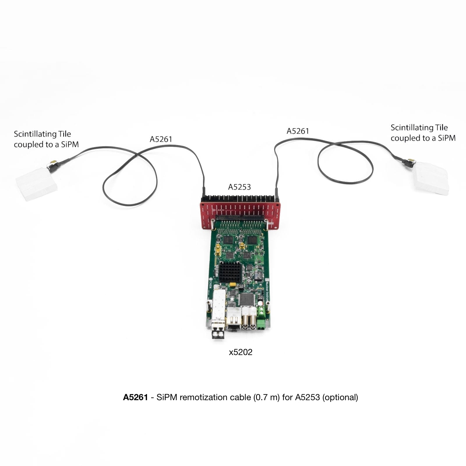
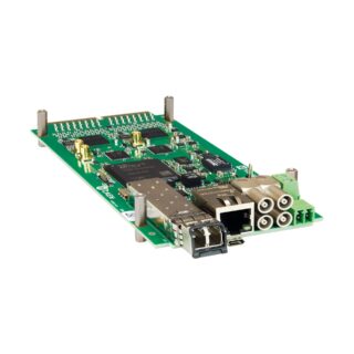
A5202 on pieni piirilevy (noin 7 cm × 17 cm), jossa on kaksi Citiroc‑1A-piiriä (yhteensä 64 kanavaa). Jokainen kanava koostuu esivahvistimesta (Preamplifier), Slow Shaper -muodostimesta pulssinkorkeuden detektorilla sekä Fast Shaper -muodostimesta ja diskriminaattorista. Kummankin Citiroc‑1A-piirin pulssikorkeusarvot muunnetaan peräkkäin 13-bittisellä ADC:llä energian mittausta varten. 64 kanavan itselaukaisusignaaleja (discriminator outputs) voidaan käyttää laskentaan, aikaleimaukseen, Time over Threshold (ToT) -informaation määrittämiseen sekä kortin bunch trigger -signaalin generointiin, joka käynnistää ADC-muunnoksen. A5202/DT5202-kortti sisältää myös piivalomonistinten biasointiin tarvittavan A7585D-virtalähdemoduulin sekä liitännät datan lukuun, synkronointiin ja ohjaukseen.
Tietolomake
Ota yhteyttä
Toni Kansanoja
- Myynti - Säteilymittaus
- Matkapuhelin: +358404824356
- toni.kansanoja@gammadata.fi

Tekniset tiedot
MECHANICAL
- Dimensions Weight: 72.8 W x 22.0 H x 174.5 L mm3 132 g
INPUTS
- 64 channels (= 2 Citiroc-1A chips)
SIGNAL POLARITY
- Positive
SENSITIVITY
- Dual range: Low Gain (LG)/High Gain (HG). Channel-by-channel individual setting of the gain value through a CSP feedback capacitor, Cf, adjustable from 25 fF to 1575 fF (25 fF step):
- LG = 1.5 pF/Cf (max gain = 60)
- HG = 10 x LG = 15 pF/Cf (max gain = 600)
DYNAMIC RANGE
- The Citiroc-1A Preamplifiers ensure a dynamic range from 160 fC to 400 pC (i.e. from 1 to 2500 photo-electrons with 106 SiPM gain)
SHAPING TIME
- Slow Shaper 7 options from 12.5 ns to 87.5 ns (12.5 ns step)
- Fast Shaper Fixed: 15 ns
FRONT PANEL I/Os
- 4 general purpose programmable LEMO I/Os connectors available:
- 2 (T0-IN and T1-IN) to be used as input (LVTTL and NIM)
- 2 (T0-OUT and T1-OUT) to be used as output (LVTTL)
- The T1-IN and T0-IN connectors are 50 Ω terminated with a jumper. The jumper can be moved to perform a bridged connection for daisy chain trigger distribution or wired-OR in a multi-board system.
DIGITAL PROBE
- LVTTL signal with different functions can be transmitted via the front panel output connectors.
ANALOG PROBE
- MCX connectors allowing the user to acquire analog signals from a specific, software selectable stage of each Citiroc-1A signal shaping chain:
- LG/HG Preamplifier output
- LG/HG Slow Shaper output
- Fast Shaper output
SELF-TRIGGERS
- Programmable 10-bit DAC for common threshold
- Minimum threshold: 1/3 photo-electron
- Separate trigger line per channel
- Programmable 4-bit DAC for channel-by-channel threshold fine adjustment
- Logic combination (AND, OR, Majority) of triggers for start of A/D conversion and time reference.
EXTERNAL TRIGGERS
- From TDlink, T1-IN or T0-IN. T0/T1 lines can be daisy chained (IN-OUT) or wired-OR (bidirectional) to share a common global trigger between multiple units.
HIGH VOLTAGE POWER SUPPLY
- Single channel PCB mounted A7585D High Voltage Power Supply:
- Common SiPM bias voltage: 20 ÷ 85 V
- Setting precision: ±0.2%±50 mV
- Individual channel adjustment: 8-bit (2.5 V or 4.5 V dynamic range, 10% tolerance)
- Max. output bias current: 10 mA (software programmable limit)
- Programmable temperature compensation
ACQUISITION MODES
- Spectroscopy Mode (PHA)
- Simultaneous acquisition of all channels
- 13-bit A/D conversion
- Systematic conversion time ∼ 10 µs (Max. trigger rate ∼ 100 kHz)
- Independent digital thresholds for channel-by-channel zero suppression (ZS)
- Counting Mode
- Channel-by-channel independent counting
- Common trigger to define counting window (Dwell time)
- Maximum counting rate (per channel): ∼ 20 Mcps
- Timing Mode
- Independent channels (merged list, time sorted)
- 0.5 LSB resolution (∼ 250 ps RMS)
- Time stamp referred to a common time reference coming from T0-IN/T1-IN connectors or from the logic combination of channel self-triggers
- Spectroscopy information (lower resolution) from Time over Threshold (ToT) information
TIME STAMP
- 56-bit counter, 8 ns step
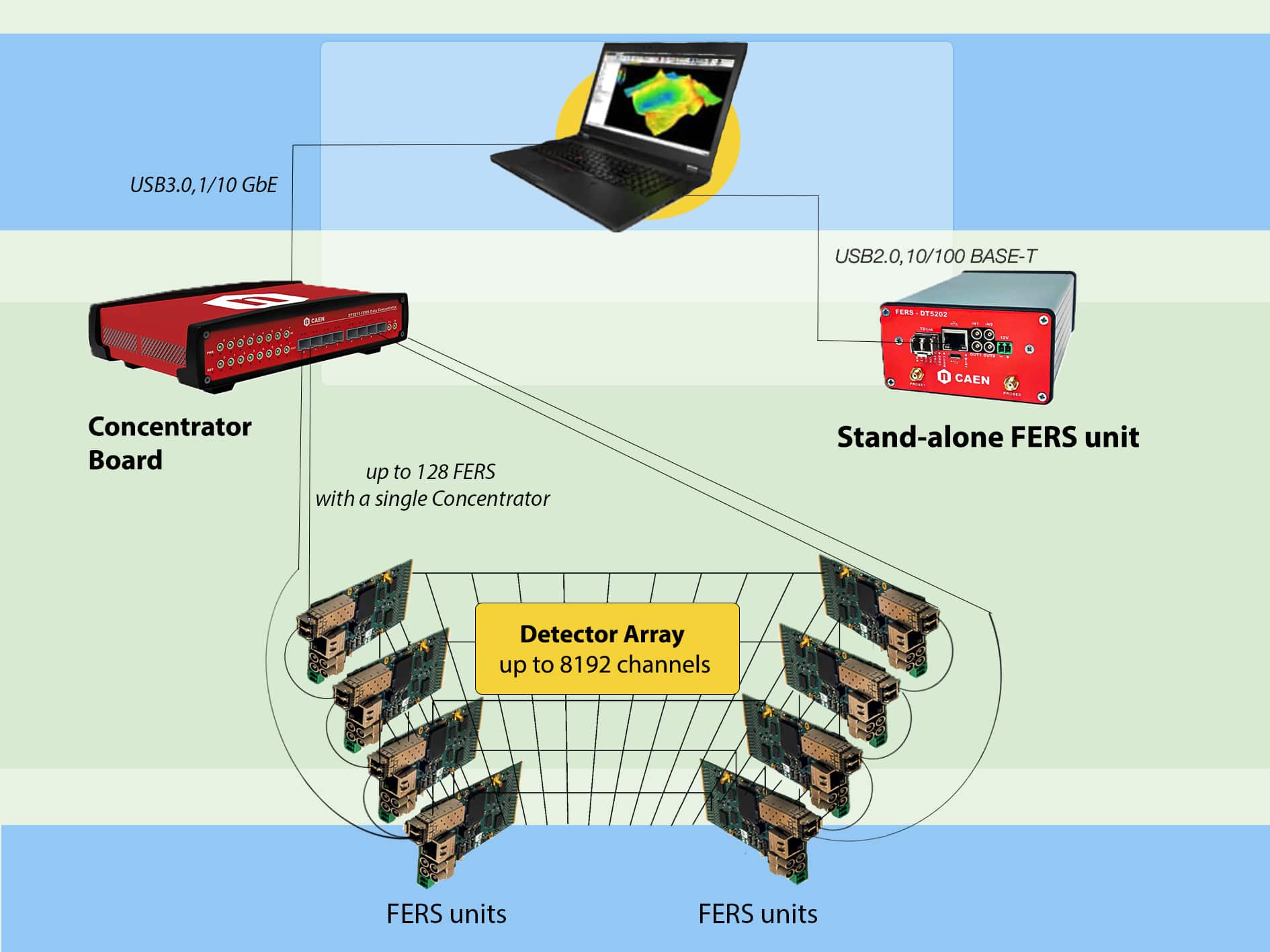
- Up to 128 boards can be synchronized with the DT5215 FERS-CB by sending a time stamp reset signal via TDlink
COMMUNICATION INTERFACES
- USB Ethernet Optical Link
- USB2.0: microUSB connector
- Bandwidth = ∼ 3 MB/s
- Ethernet connector, type Rj-45. Supports 10/100 Mbit/s connection to a PC
- Bandwidth = ∼ 2.5 MB/s
- Optical Link
- Small Form Factor Pluggable (SFP+) transceiver component for optical connection (3.125 Gbit/s). TDlink CAEN proprietary protocol allows for multi-board synchronization, slow control and data readout
- Data Concentrator DT5215 required
FIRMWARE
- Firmware can be upgraded via USB, Ethernet or Optical Link (starting from firmware revision 7.5)
- Firmware of μC can be upgraded via Ethernet only
SOFTWARE
- Readout SW
- Fully controlled by the Janus open source software for Windows® and Linux®.
- It can run in console mode (C program, with console commands and gnuplot display for plots) or connected to a GUI (Python) that implements user friendly configuration panels and run controls.
- Janus can acquire, plot and save output files with PHA, ToT histograms, as well as list files (energy and timestamp for each channel).
- Web Interface
- Board information and monitoring, Ethernet configuration.
POWER REQUIREMENTS
- Single power supply (+12 V). Regularly working in a range between +7 V and +15 V
POWER CONSUMPTIONS
- 750 mA @ +12 V, i.e. ≈ 9 W (acquisition on, all channels enabled, HV on, 64 SiPMs mounted)
- 685 mA @ +12 V, i.e. ≈ 8.2 W (acquisition off, all channels enabled, HV off, no SiPMs mounted)