A5202 & DT5202


Need help?
We help you find the right solution. We offer support, service, calibration and training for all our products. Contact us for a service agreement!
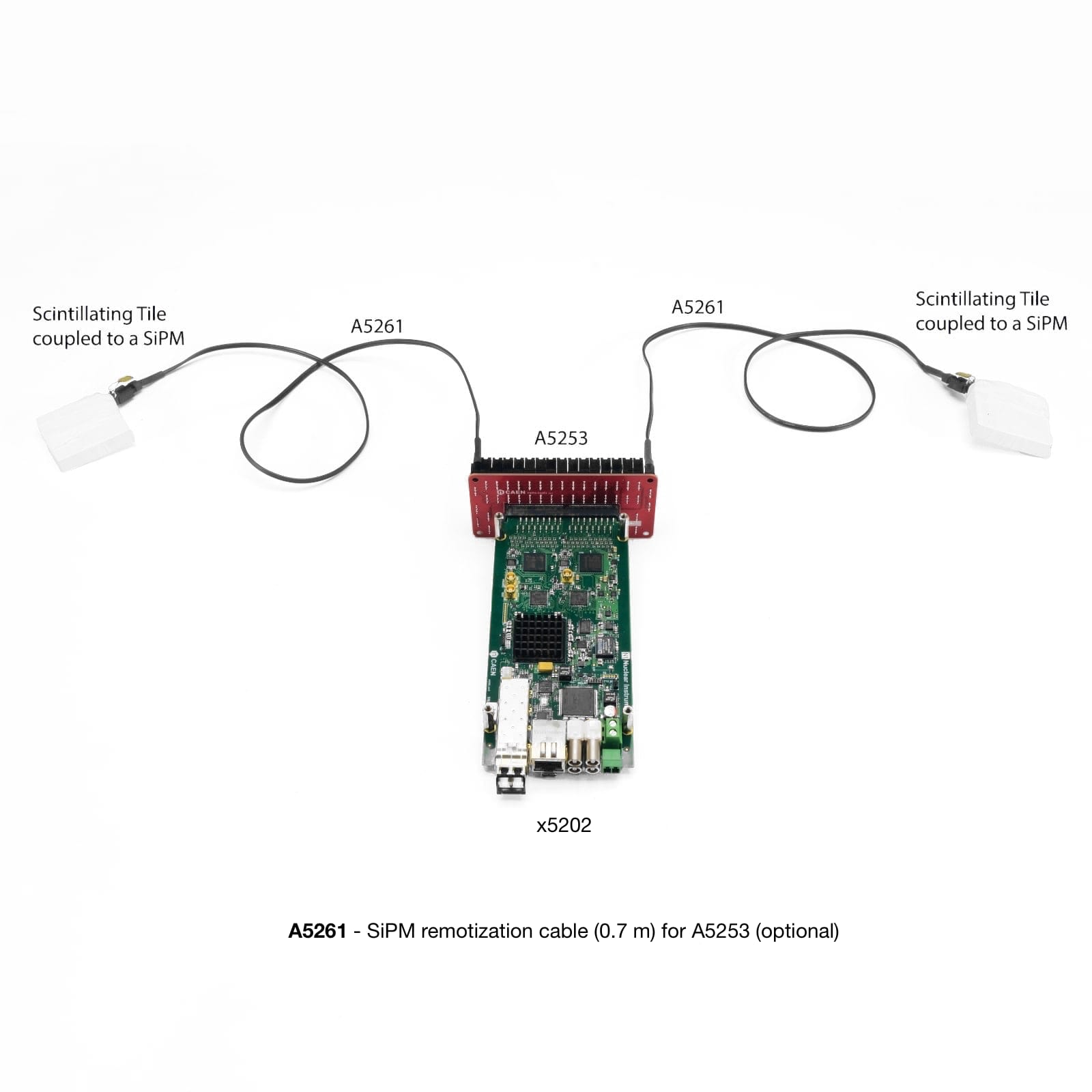
Service & reparation Request a quoteThe A5202 is a small board (~ 7 cm x 17 cm) housing two Citiroc-1A chips (64 readout channels). Each readout channel is composed of a Preamplifier, a Slow Shaper with pulse height detector, and a Fast Shaper followed by a discriminator. Pulse height values from each Citiroc-1A are converted sequentially by a 13-bit ADC to perform energy measurements. The 64 channel self-triggers (discriminator outputs) can be used for counting, time stamping, to determine the Time over Threshold (ToT) information, and also to generate the board bunch trigger that starts the ADC conversion. The A5202/DT5202 board also integrates the A7585D power supply module necessary for biasing the SiPMs, and the interfaces for readout, synchronization, and control.
Data sheet
Contact
Toni Kansanoja
- Sales - Radiation Detection
- Mobile: +358404824356
- toni.kansanoja@gammadata.fi

Technical specification
MECHANICAL
- Dimensions Weight: 72.8 W x 22.0 H x 174.5 L mm3 132 g
INPUTS
- 64 channels (= 2 Citiroc-1A chips)
SIGNAL POLARITY
- Positive
SENSITIVITY
- Dual range: Low Gain (LG)/High Gain (HG). Channel-by-channel individual setting of the gain value through a CSP feedback capacitor, Cf, adjustable from 25 fF to 1575 fF (25 fF step):
- LG = 1.5 pF/Cf (max gain = 60)
- HG = 10 x LG = 15 pF/Cf (max gain = 600)
DYNAMIC RANGE
- The Citiroc-1A Preamplifiers ensure a dynamic range from 160 fC to 400 pC (i.e. from 1 to 2500 photo-electrons with 106 SiPM gain)
SHAPING TIME
- Slow Shaper 7 options from 12.5 ns to 87.5 ns (12.5 ns step)
- Fast Shaper Fixed: 15 ns
FRONT PANEL I/Os
- 4 general purpose programmable LEMO I/Os connectors available:
- 2 (T0-IN and T1-IN) to be used as input (LVTTL and NIM)
- 2 (T0-OUT and T1-OUT) to be used as output (LVTTL)
- The T1-IN and T0-IN connectors are 50 Ω terminated with a jumper. The jumper can be moved to perform a bridged connection for daisy chain trigger distribution or wired-OR in a multi-board system.
DIGITAL PROBE
- LVTTL signal with different functions can be transmitted via the front panel output connectors.
ANALOG PROBE
- MCX connectors allowing the user to acquire analog signals from a specific, software selectable stage of each Citiroc-1A signal shaping chain:
- LG/HG Preamplifier output
- LG/HG Slow Shaper output
- Fast Shaper output
SELF-TRIGGERS
- Programmable 10-bit DAC for common threshold
- Minimum threshold: 1/3 photo-electron
- Separate trigger line per channel
- Programmable 4-bit DAC for channel-by-channel threshold fine adjustment
- Logic combination (AND, OR, Majority) of triggers for start of A/D conversion and time reference.
EXTERNAL TRIGGERS
- From TDlink, T1-IN or T0-IN. T0/T1 lines can be daisy chained (IN-OUT) or wired-OR (bidirectional) to share a common global trigger between multiple units.
HIGH VOLTAGE POWER SUPPLY
- Single channel PCB mounted A7585D High Voltage Power Supply:
- Common SiPM bias voltage: 20 ÷ 85 V
- Setting precision: ±0.2%±50 mV
- Individual channel adjustment: 8-bit (2.5 V or 4.5 V dynamic range, 10% tolerance)
- Max. output bias current: 10 mA (software programmable limit)
- Programmable temperature compensation
ACQUISITION MODES
- Spectroscopy Mode (PHA)
- Simultaneous acquisition of all channels
- 13-bit A/D conversion
- Systematic conversion time ∼ 10 µs (Max. trigger rate ∼ 100 kHz)
- Independent digital thresholds for channel-by-channel zero suppression (ZS)
- Counting Mode
- Channel-by-channel independent counting
- Common trigger to define counting window (Dwell time)
- Maximum counting rate (per channel): ∼ 20 Mcps
- Timing Mode
- Independent channels (merged list, time sorted)
- 0.5 LSB resolution (∼ 250 ps RMS)
- Time stamp referred to a common time reference coming from T0-IN/T1-IN connectors or from the logic combination of channel self-triggers
- Spectroscopy information (lower resolution) from Time over Threshold (ToT) information
TIME STAMP
- 56-bit counter, 8 ns step
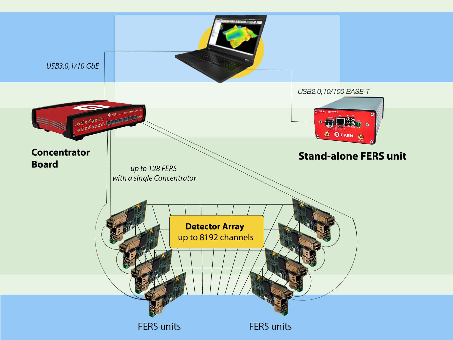
- Up to 128 boards can be synchronized with the DT5215 FERS-CB by sending a time stamp reset signal via TDlink
COMMUNICATION INTERFACES
- USB Ethernet Optical Link
- USB2.0: microUSB connector
- Bandwidth = ∼ 3 MB/s
- Ethernet connector, type Rj-45. Supports 10/100 Mbit/s connection to a PC
- Bandwidth = ∼ 2.5 MB/s
- Optical Link
- Small Form Factor Pluggable (SFP+) transceiver component for optical connection (3.125 Gbit/s). TDlink CAEN proprietary protocol allows for multi-board synchronization, slow control and data readout
- Data Concentrator DT5215 required
FIRMWARE
- Firmware can be upgraded via USB, Ethernet or Optical Link (starting from firmware revision 7.5)
- Firmware of μC can be upgraded via Ethernet only
SOFTWARE
- Readout SW
- Fully controlled by the Janus open source software for Windows® and Linux®.
- It can run in console mode (C program, with console commands and gnuplot display for plots) or connected to a GUI (Python) that implements user friendly configuration panels and run controls.
- Janus can acquire, plot and save output files with PHA, ToT histograms, as well as list files (energy and timestamp for each channel).
- Web Interface
- Board information and monitoring, Ethernet configuration.
POWER REQUIREMENTS
- Single power supply (+12 V). Regularly working in a range between +7 V and +15 V
POWER CONSUMPTIONS
- 750 mA @ +12 V, i.e. ≈ 9 W (acquisition on, all channels enabled, HV on, 64 SiPMs mounted)
- 685 mA @ +12 V, i.e. ≈ 8.2 W (acquisition off, all channels enabled, HV off, no SiPMs mounted)